The new intake manifold

So after looking into the mass of ideas from OEM and aftermarket intake manifolds, I’ve decided on a design.
It’s a long runner, fairly large plenum, and big throttle design.
Here is the preliminary layout.

image

image

The long tubes need about 3″ cut off the length, then a slash cut on the top. The injectors will be at an angle toward the firewall, they shouldn’t interfere with the heater hoses. I’ll only be able to use the shorty injectors from the looks of it. Good thing I have those, instead of the tall ND/Rochester style.
I’m going to attempt at drawing the whole thing in cad first.

The smell of fresh paint in the air.

image

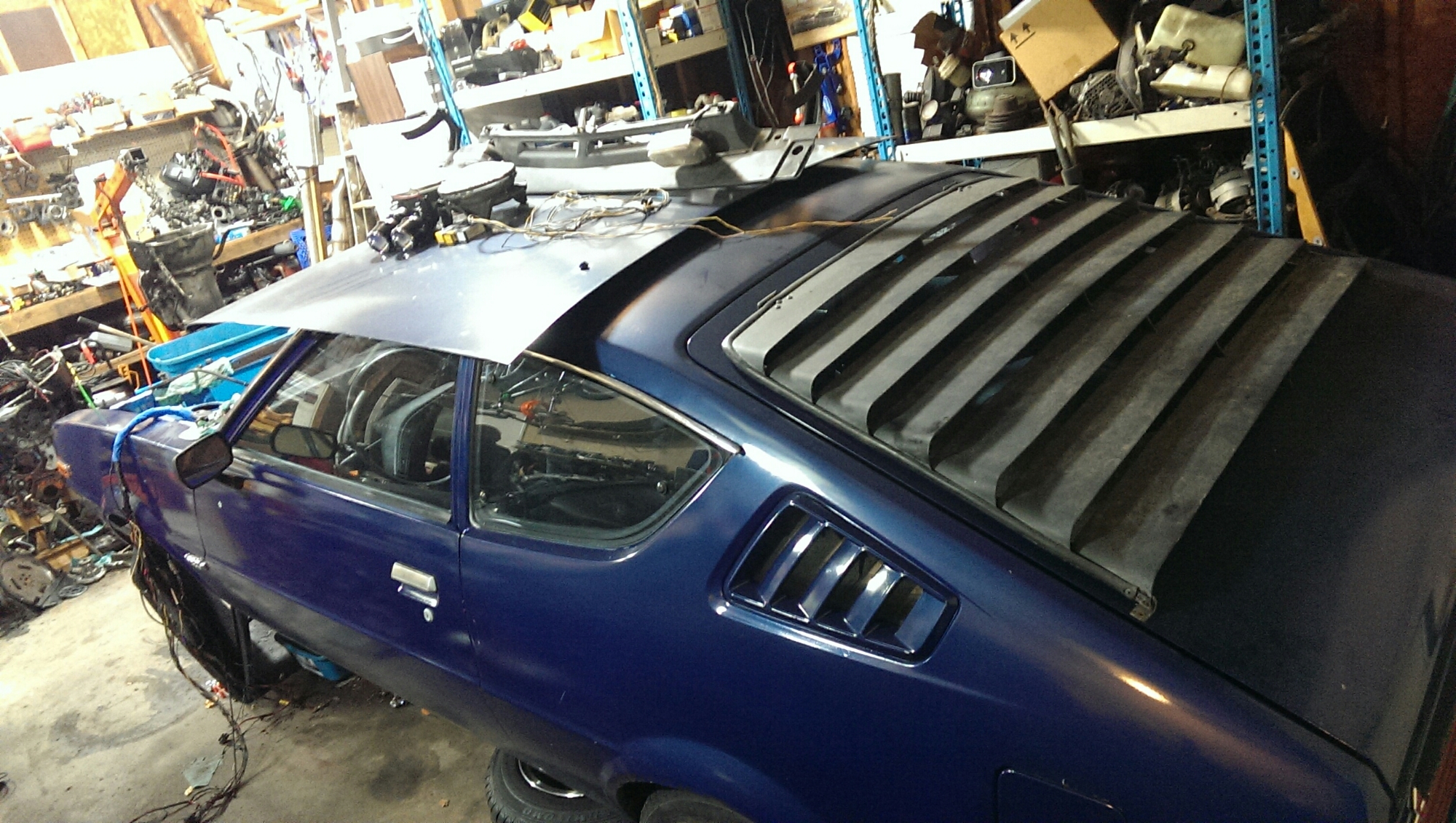
I laid some primer down in the engine bay, and on the louvers. The engine bay, then got a coat of Bahama blue (gm color), because it comes closest to the “bright blue” used by mitsu/chrysler.

image
I was thinking of going back to a mechanical fan, but I think I’d rather have that power to the wheels, and just use an electric fan.
image

The louvers got a fresh splatter of bed liner. The engine bay got a nice shot of clear coat over the banana blue.
image

Looking fresh.
I ordered parts for actual performance stuff, so I’ll take a break on body junk. But I think this arrow might be getting the jet package. Well, a DIY version of it.

Baffling. And so on.

image

The baffle that I’m installing will help regulate the oil from getting sloshed back in the pan on acceleration. It will allow the oil to flow back to the front, or back to the lowest point, with no real change. I also installed the turbo drain pipe in the pan. I didn’t have enough room to just use a compression type port hole, so I welded it on, inside and out. This is Mitsubishi Japanese steel! None of that “American sheet metal”.

image

I installed a supplementary trash magnet as well. You can see it through the drain hole so it can be checked easily during an oil change. The drain plug also is magnetic. The extra is a rare earth magnet from the inside of a hard drive.

image

image

I started mocking up an exhaust manifold. I planned to do a tri-y design, but I don’t think that will work out as I wanted to put a twin scroll flange on it so I could install a turbo after the motor is broke in and tuned non-turbo. I think I’ll just make a basic long tube header. I’ll do that once the engine is installed.

image

image

image

I sprayed the lower section of the engine bay with bedliner. The end result will be two-tone. I found a paint the matches the stock “bright blue” pretty well.

image

Adam bought a house and was real excited that prohibition ended back in 33. So we celebrated!

Getting head

I got the front cover and water pump installed.

image

The next step was the head.

image

That went on pretty smooth. Iused the same arp ultra torque, on the threads and on the shoulders of the head bolts. After assembling, everything rotated smoothly. You can hear the cylinders breathing.
Then I had to check my louvers fitment.

image

They will look nice. I need to make the side louvers match.

Bolts and nuts.

Today is engine assembly day.
There is a lot to do.
Everything of mine has already been cleaned. Make sure everything is clean. Clean anything that isn’t clean. In case you haven’t noticed, you want to be clean when you are assembling an engine.
So, first step, clean. Second step, lube.
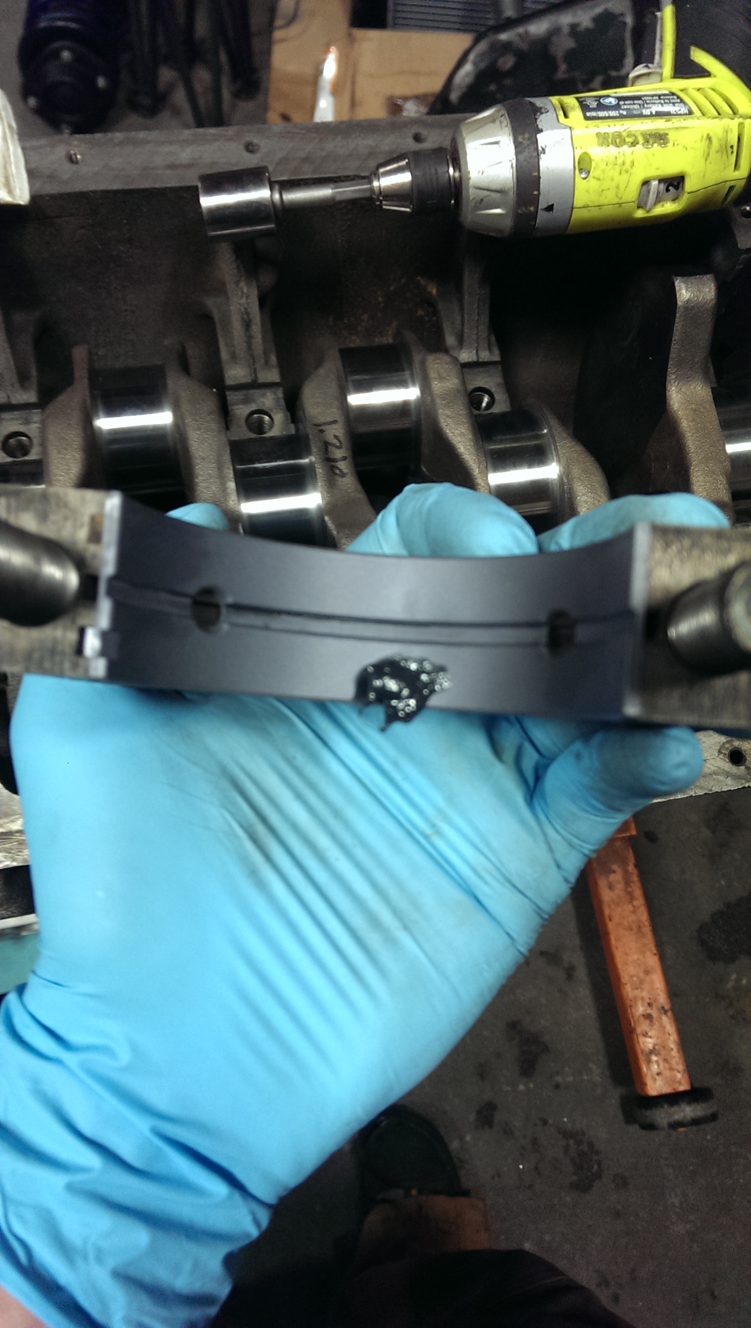
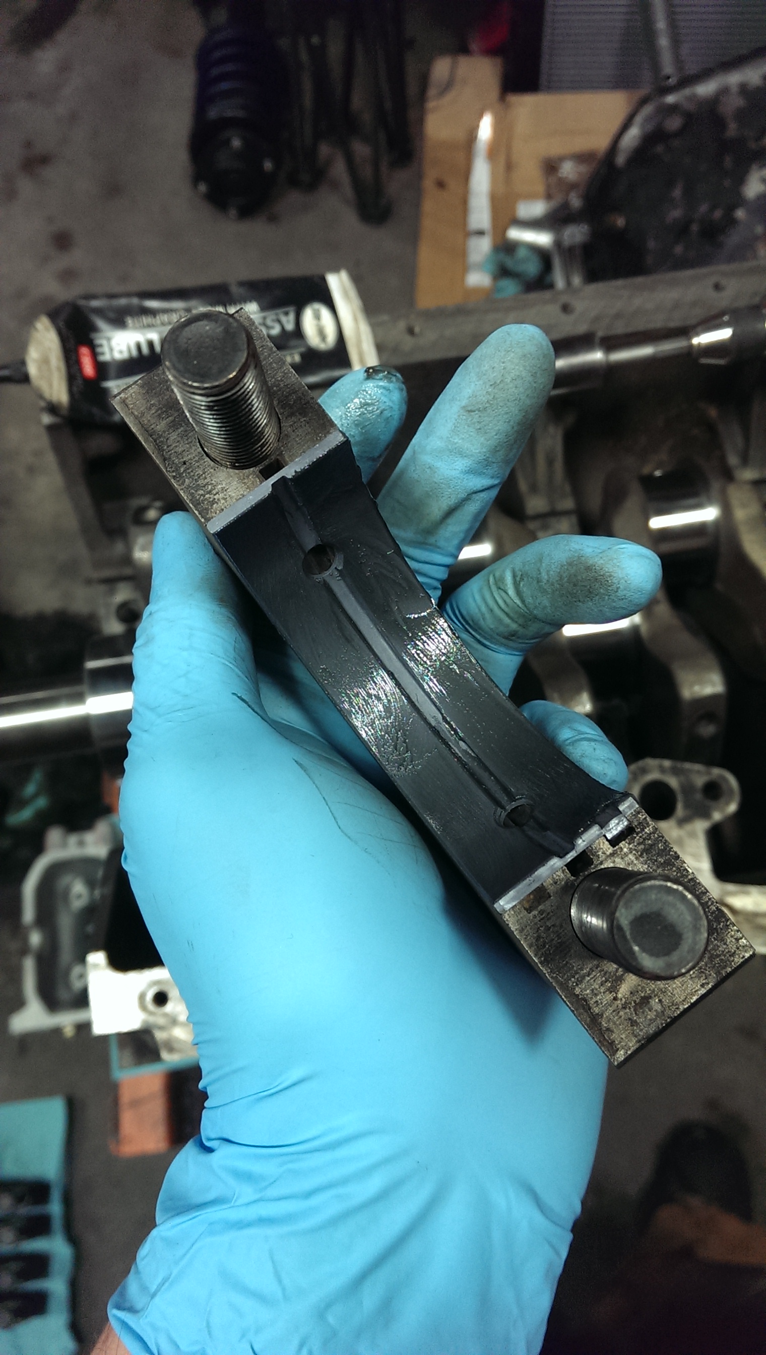
I start with a glob of moly assembly lube, then spread it out. I try not to get any in the oil groove.
image

image

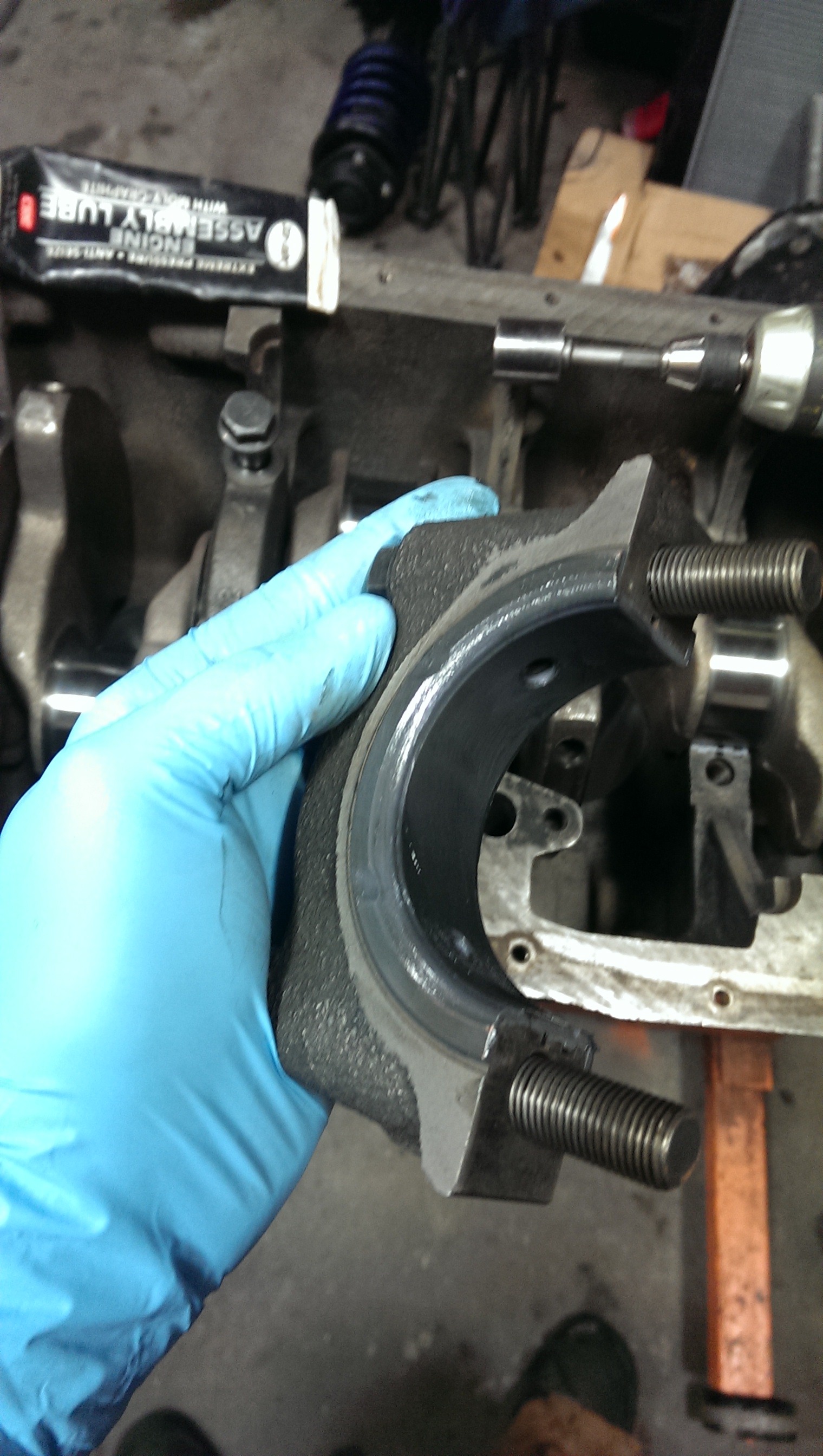
Also, get the side of the thrust bearing.
image

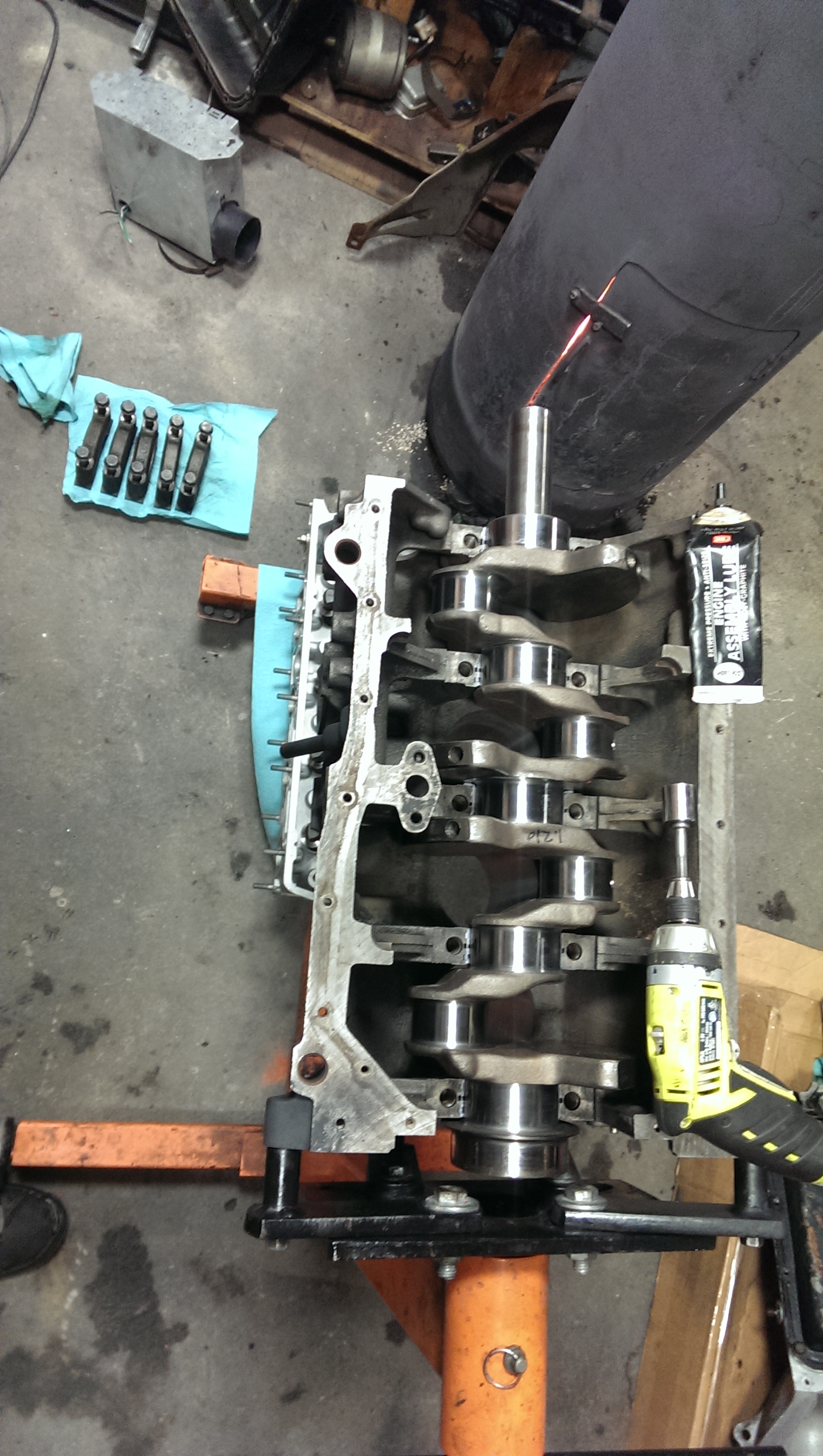
Once the bearings are lubed and installed in the block and caps, install the crankshaft.
image

Then I’ll install the bearing caps.

image

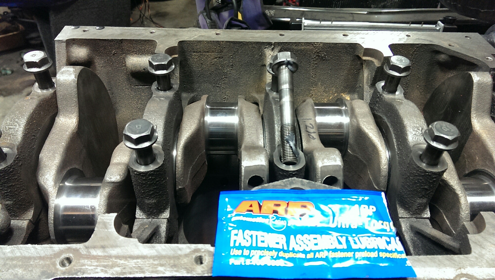
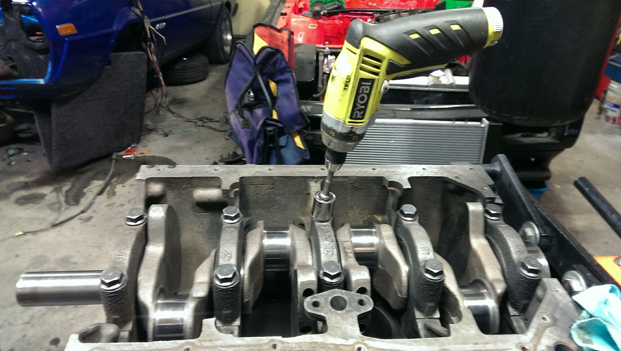
I prefer to use arp ultra torque. Even if I’m not using arp fasteners. You could use oil, or assembly lube.
I cheat a little and pretorque the bolts with my ryobi. I think it only goes up to 20, but I dial it back to 16 or so.
image

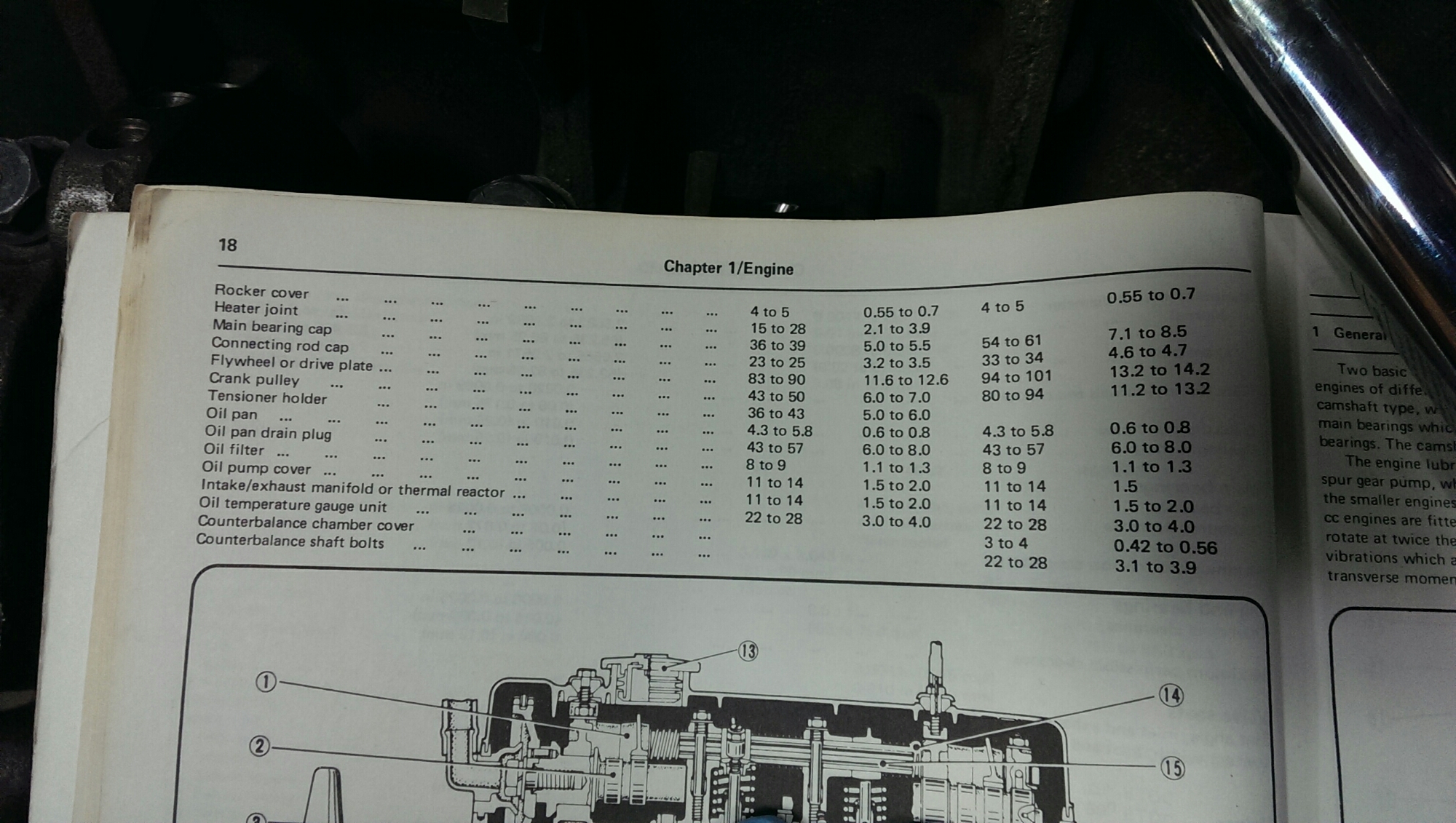
Then, torque them to spec. I’m going to use the same setting I used when I plastigauged the crank, 60 ft/lbs.
image

Once the crank is bolted in, I’ll flip the block over, or on its side, to start installing the pistons.
image

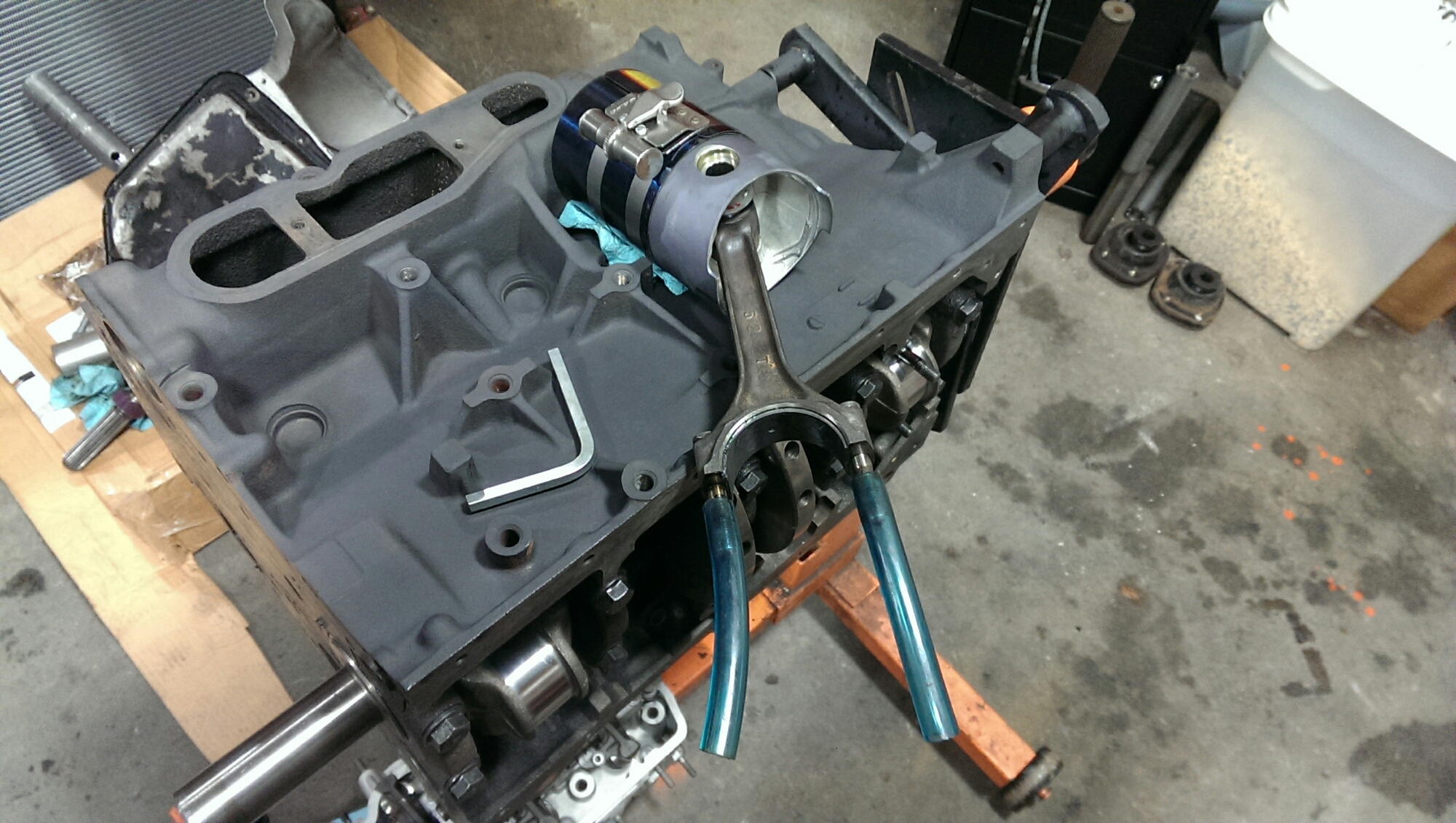
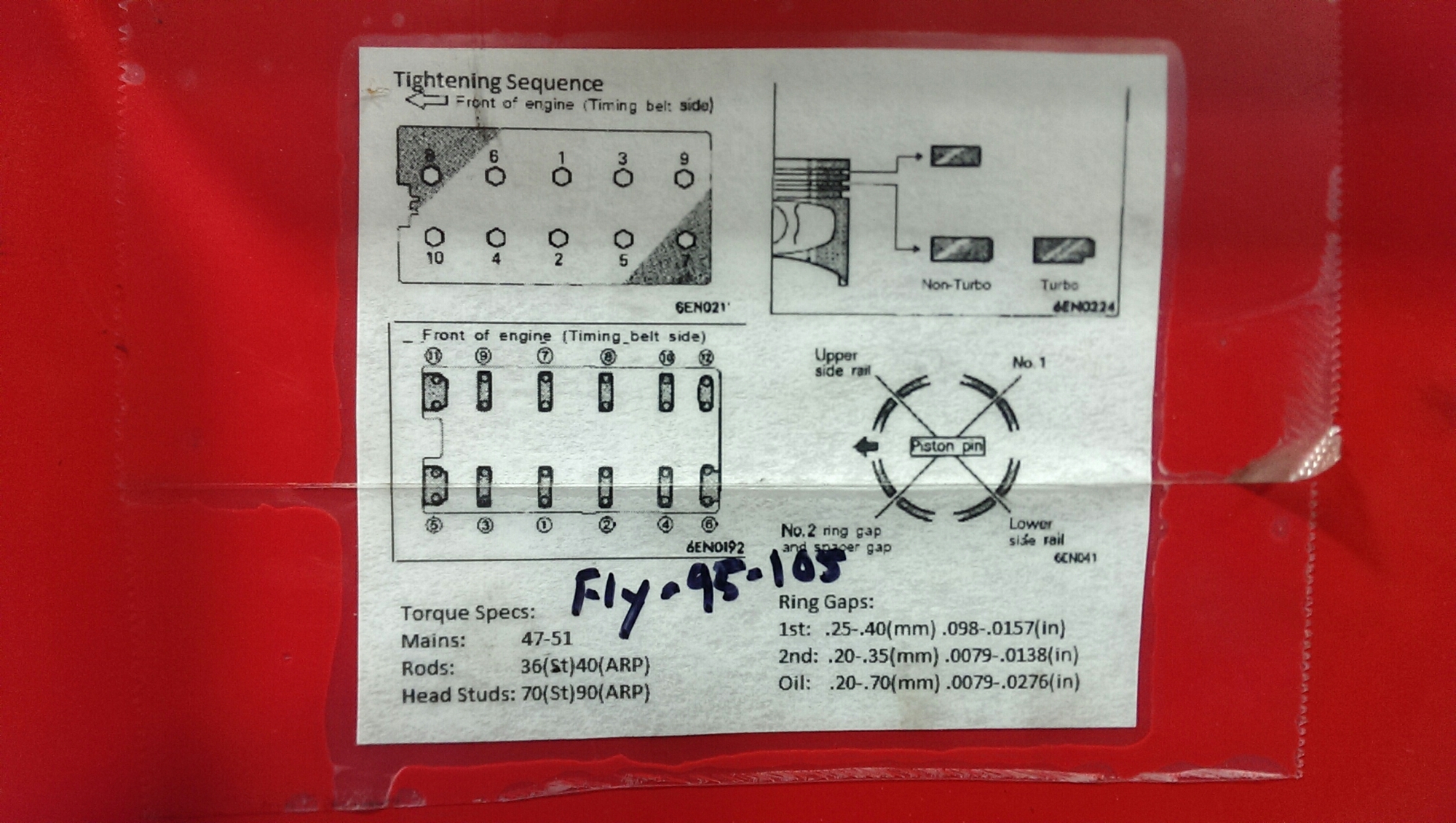
Proper ring placement is important.

image

In order not to scratch the newly ground crankshaft, I’m using pieces of silicone hose. They also help give an indication of how far, or how straight the piston is.
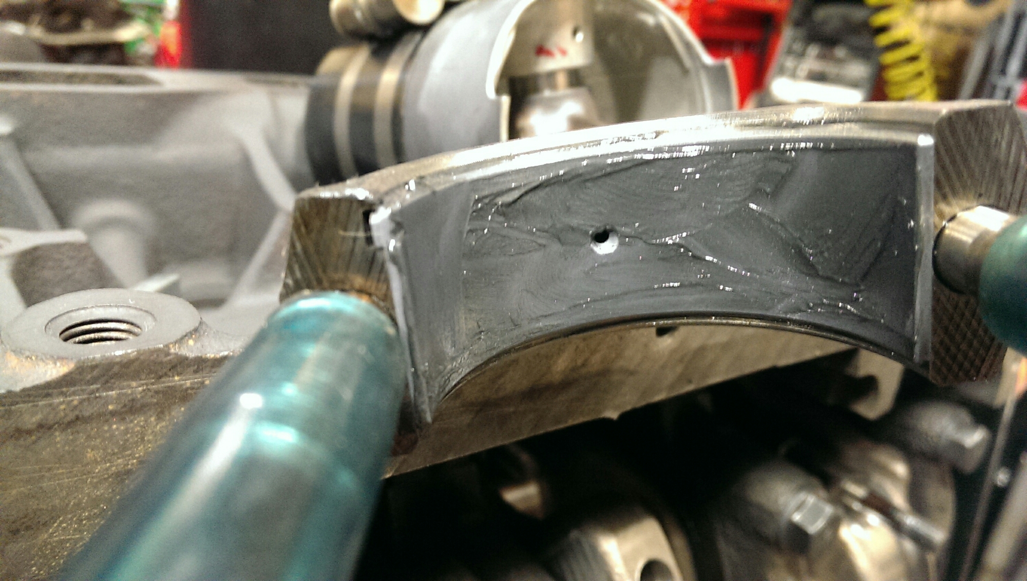
When I apply assembly lube to the big end caps, I try not to pack it in the hole.
image

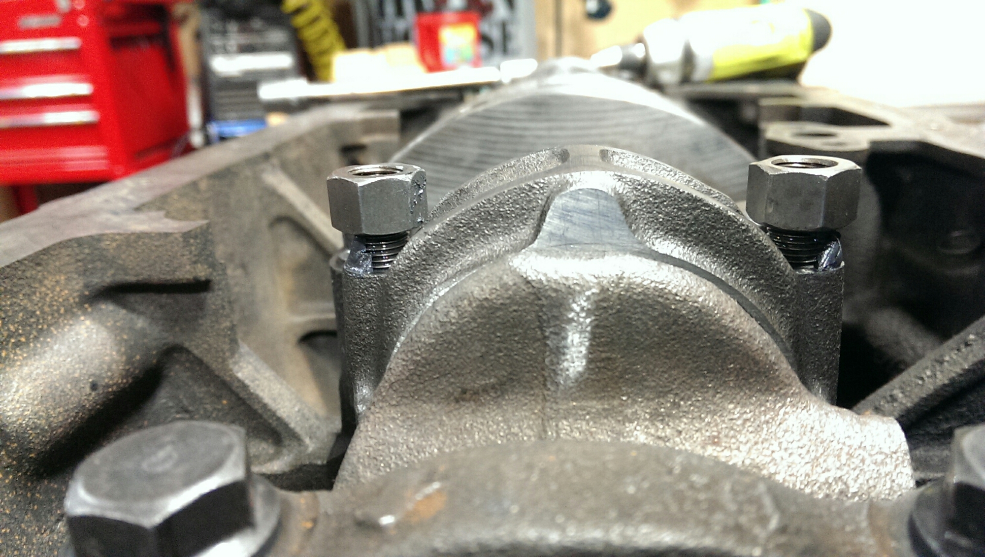
I apply the ultra torque to the rod bolts, and nut base like so. Also torque to the same spec as plastigauged.
image

Then you should be able to rotate the assembly with a bit of effort. If you can’t rotate it, something went wrong.
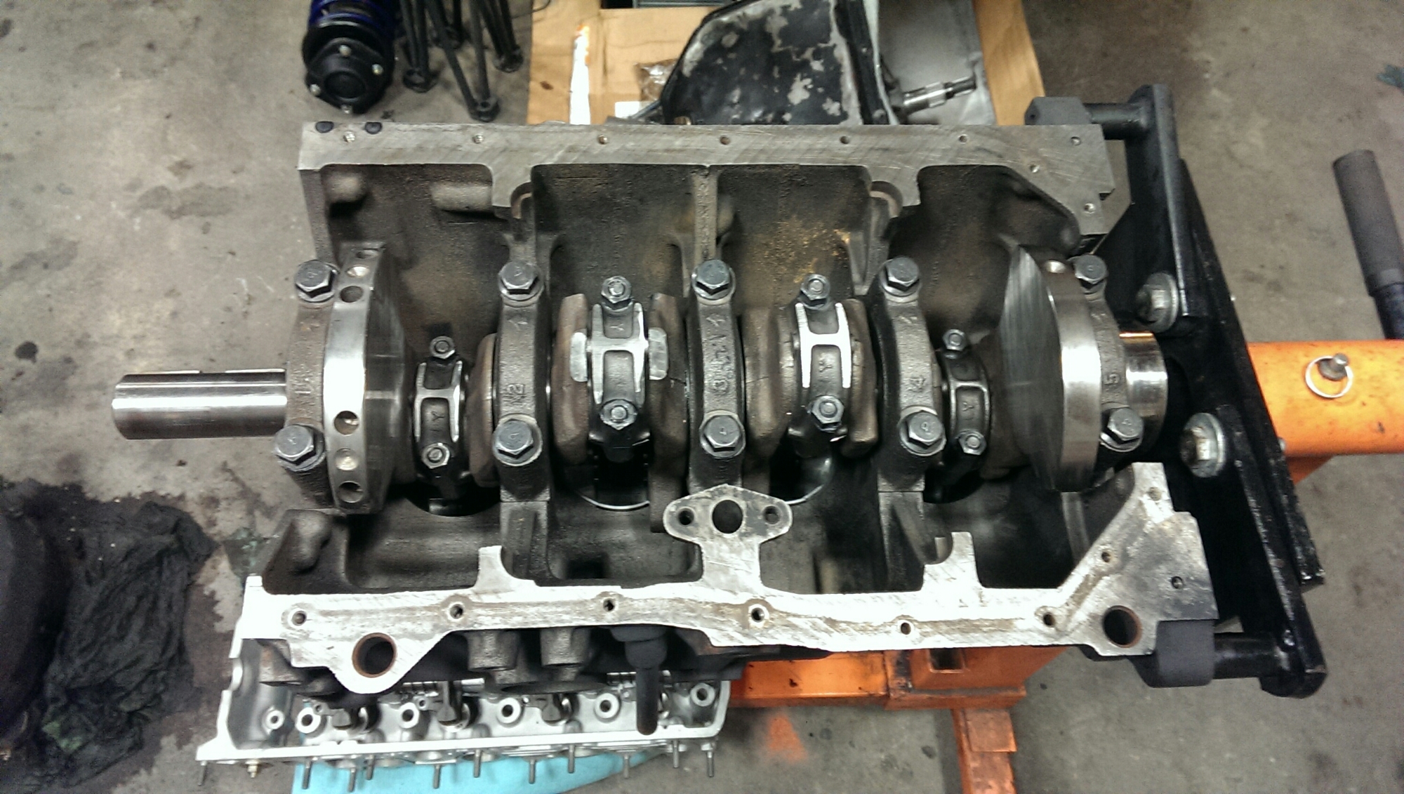
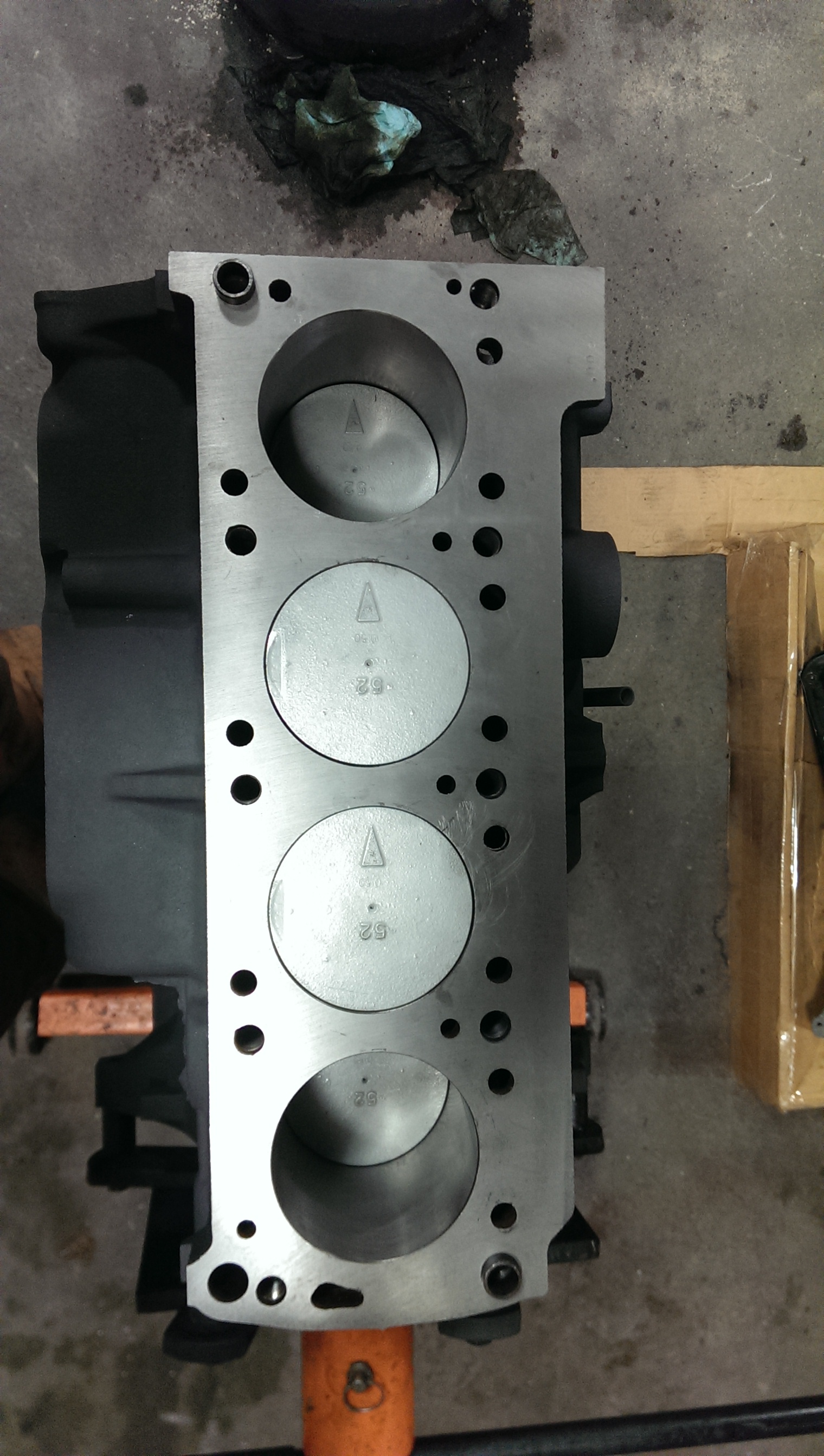
image

image

The last thing I did, was setup the timing components.
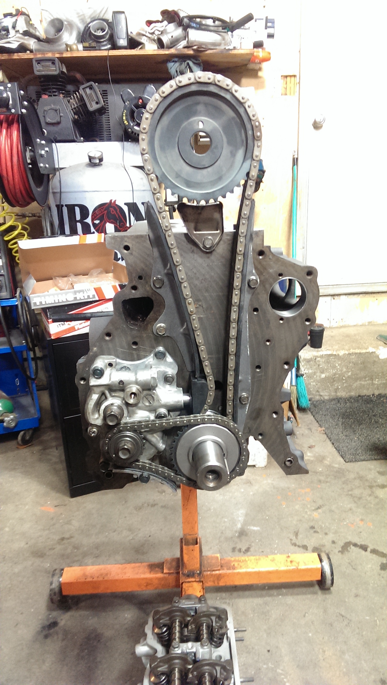
image

It’s a little puzzle in itself, just because you have to align key ways, pins, dots and links.
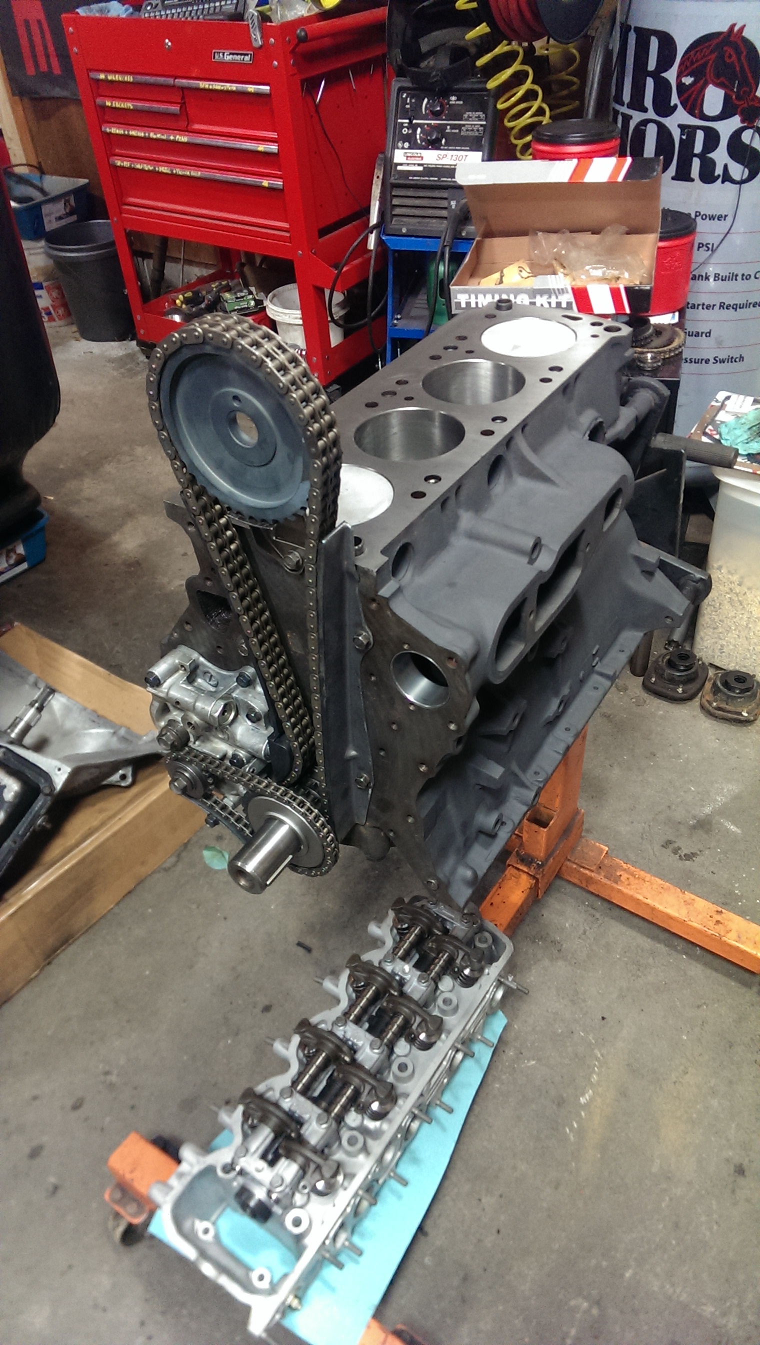
image

Oh the joy.

The engine rebuild

The engine rebuild is in a paused state at the moment. Everything was looking good until I test fit the thrust bearing. I knew I should have brought the bearings to shaker for reference.

image

The width on the crank is 1.210″, the bearing width is 1.220″. That surely won’t fit. So if both sides get .007″ trimmed off, that should give me my .002-.007″ clearance.
The mains do check out to .003″ clearance, max is .005″.

image

image

I swapped over the G54b turbo cam from the conquest, along with the hydraulic rocker assembly.
The top two rings are gaped to .29mm, and the oil rings are .35mm.
I have not plastigauged the rod bearings, but they calculate out to .0015″ clearance.

image

And now I wait, and clean.

image

Ewwww.